Thursday, December 25, 2008

V-Berth insulation and hanging locker

Two layers of insulation was installed on the hull in the V-berth in the same manner as in the head. The front and side panels for the hanging locker were installed with a piece of Jatoba cut and routered to join the two panels. Several coats of Min Wax Wipe On Poly was applied to the panels before installation. Epoxy fillets were applied to the panel at the hull.

Thursday, December 18, 2008

Snow Day

Tried to get to the shop in my 4x4 jeep Cherokee today but did not make it. We had 28 inches of snow last night and the driving conditions were horrendous. The shop is on a dead end road that is not maintained, when the plow went by on the main road it created a large berm that was impassible. Spent the morning digging out stuck cars and picking up stranded people walking along the roads and getting them to where they were going.
After that Goldie (my "super" dog) and I drove back home and played in the backyard for a few minutes. The snow was over her head as she plowed and hopped through it.

Super dog!

Goldie and I in the back yard


Tuesday, December 16, 2008

Head

I decided to take a break from being scrunched up working under the cockpit and started working on the head so I could work more comfortably for a while. I sat across from the head and visualized the components and where they might go. I cut some plywood, made a mock-up, and placed the toilet on the plinth and stared at it until I had a good picture in my mind of what I wanted to build.

I decided to make the front in two panels, the top with a hinged door in it and the bottom with a removable access hatch to get at the mechanical in the space behind. Templates were made in the usual manner with a hot glue gun and two inch wide strips of 1/8" plywood. The templates were placed onto teak plywood, the outlines drawn and the teak cut to shape and test fit. The access holes were cut and a piece of solid wood that would be used to join the two panels was cut and routered and sanded to fit. The top panel is 90 degrees to the plinth. The lower panel is offset 11 degrees to match the angle of the toilet back. The solid wood stock will have a two inch setback forming a little shelf to accommodate the offset of the two panels. The wood was taken home to have the finish applied. Eleven coats of Wipe On Poly was applied and the pieces were sanded with 600 grit paper every three coats. Applying the finish took several days to complete.

While waiting for panels to be ready I started preparing the head area. The fiberglass was sanded and cleaned. The listings for the panels were installed and the mounting pads for the strainer, pump, and vented loop were fabricated and epoxied into place and filleted. The space behind the panels was painted with Pettit Dura White paint, Pettit claims mould and mildew will not grow on this paint. I have not been able to get the paint to flow and level well regardless of the technique used to apply it. Several types of rollers were tried as well as rolling and tipping, and applying with good quality badger brushes. The finish is suitable for lockers but I will have to experiment with it further to see if I can get better results for use in the cabin.

Several layers of biaxial cloth was applied to seal the 1-1/2" hole in the hull where the old toilet discharged directly overboard. A location was chosen for the intake thru-hull and several layers of biaxial cloth was applied to the hull starting with a large piece and gradually reducing each subsequent piece in size. The next day the adapter flange was test fit and epoxy with high density filler was used to level the area under the flange. This method makes for a very strong, thick base for the thru-hull assembly and a traditional wood backing plate is not required. The problems of compression fatigue and breakdown or rot of a traditional wood backing block is eliminated.

Contact adhesive was sprayed onto the hull and onto the Double-bubble insulation that was previously cut to a slightly larger size than required. The insulation was then pressed into place and a razor knife was used to trim the edges. Shrink wrap tape was used to join seams. A heat gun was used to warm the tape and ensure it would not separate with age. If you don't use heat on the tape it often will lift with age. If you use heat it is extremely difficult to remove and will not lift with age.

The strainer, pump, and vented loop were installed. Vetus water hose was used and Awab hose clamps with red rubber tips to cover the sharp tail of the clamps finished the assembly.

I was really impressed with the quality of the Vetus hose. It has a smooth inside wall, and its ability to bend to a tight radius without placing a stress load on fittings is impressive. In the picture below I can easily hold the tight radius with a couple of fingers. Other similar hoses I have used that can bend a tight radius have put a significant stress load on the fittings when doing so and require additional and sturdy fasteners to prevent fitting fatigue.

I took the panels up into the boat and test fit them with the toilet in place. I'm happy with the fit and will set them aside for installation at a later date after the plumbing is completed. The lower hatch is large enough for me to get one arm and my head comfortably into. The top hatch is large enough to get two arms and my head into so I can work on the chain-plates when required.


Thursday, December 4, 2008

Thru Hulls

The time has come to dry fit the cockpit drain thru-hulls in order to ensure proper clearance of the ball valve handles etc. The holes in the hull were enlarged from 1-1/4" to 1-1/2" to allow for faster drainage of water when the cockpit is pooped. The hull thickness was measured, the thru-hull cut to length, and the complete assembly was dry fit into the hull.
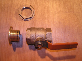
The assembly we used consists of a thru-hull, adapter flange, ball valve, and hose adapter (not shown) as shown in photo one below. Various thru-hulls and strainers are available that have the flange built into them (such as the sea cock in photo two). I opted to use a Groco adapter flange as we often sail to remote locations and it is far easier to procure a bronze ball valve from a local hardware store then it is to order one with the flange built into it and wait several days or weeks for one to arrive and have to deal with getting it through customs in foreign ports, a task that often requires hiring a customs agent at considerable expense. The adapter flange has straight thread for the thru-hull and tapered thread for the ball valve.
As a marine surveyor I often see ball valves installed directly onto thru-hulls, as shown in photo three. This is an incorrect and potentially dangerous installation and should NEVER be done. Thru-hulls are straight thread, ball valves are tapered pipe thread. When you assemble the two the threads bind almost immediately and you have two or at best three threads holding as indicated by the black line on the thru-hull in photo three. I marked this with a felt pen after tightening with tools to demonstrate how little thread is engaged. With constant vibration or a mis-step onto the fitting the joint is compromised and the vessel can be flooded very quickly.

PHOTO ONE


PHOTO TWO

PHOTO THREE


Monday, November 24, 2008

Galley bulkhead / Starboard Settee

Using Template material I made a mock-up of the galley bulkhead and using 1/4" plywood made a template of the front of the starboard settee. When I was satisfied with the template I drew it out onto 1/4" teak and cut it too shape. Several 4-1/2" holes were cut in the back piece to lighten it and the two pieces were laminated together. After another test fit and trimming as required I applied several coats of satin Wipe on Poly made by Minwax.


Laminating the pieces together

Test fitting

Back of the piece

Applying Wipe on Poly


Stairs replace the ladder

Dangerous (thats the name he likes to go by), A good customer and fellow builder was done with his project and gave our shop the stairs he built to get aboard his boat. Gary (my boss) said they'd be perfect for getting aboard my boat and told me I can have em for the duration of my project. They are a welcome addition to the project.

Dangerous also donated a bunch of Jatoba lumber that Gary told me I could have.

A big thank you to both Gary and Dangerous!

Epoxy Metering Pump

The shop bought a metering pump for west System Epoxy that pumps both the resin and hardener at the same time. I put it too use dispensing resin for my projects, making several batches and randomly testing the unit for accuracy by holding small graduated measuring cups under each spout to ensure it was dispensing at the correct ratio. I am very impressed by this unit and wish we'd have bought one sooner. It is simple to use and a great time saver and is very accurate.


Holding Tank

With no good choice available for a drop in pre-made holding tank I decided to incorporate one into the hull. After the new ballast cap was laid up (with three layers of biaxial cloth) three layers of biaxial cloth was applied to the hull forming the tank sides. The top and baffle was templated in the usual manner and the parts laid up in the shop and then trimmed to fit. The baffle and the tank fittings were installed, then the top was glassed into place using three layers of biaxial cloth on all seams. West System epoxy was used for the project and the mixture was made slightly resin rich as recommended by West system when building tanks.


Thursday, August 28, 2008

Moving the boat to the shop

This is our busy time of year at the shop so I have not had the time to post as often as I'd like.
A lot has been done since my last post. I'll add more pictures soon as time permits.
The hull stiffeners are completed. Three layers of biaxial cloth was glassed over the ballast pig forming a new cap and an 18 gallon holding tank was glassed into the hull.
The prop shaft, stuffing box and stern tube were removed and the old glass ground out and three layers of biaxial glass was applied.
The aft (cabin) bulkheads were installed as were the partitions in the lazzerette and under the cockpit. The floor partitions were installed and a temporary floor put down.
A customer who had the same little diesel as I salvaged out of the O'day made me an offer I could not refuse and bought the diesel from me. His was not repairable and mine was a drop in replacement for it. I purchased an electric motor, controller, etc and will be putting them into the vessel this winter.
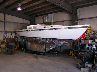
Last week we moved the vessel from the back yard of my home to the shop where I work and it will be stored inside a heated building for the winter so I can continue the project during the cold weather. Last winter we had several trees come down, some uncomfortably close to the vessel, I am grateful to my boss and good friend Gary Dawes for letting me bring the vessel to the shop for the winter! He says he likes the fact that I can't call in sick to work on my boat anymore! :-)

Placing the yard arm jacks

Nick (foreground) and Scott our professional boat movers chaining up for the lift. Thanks for doing a great job on the move! You guys are the best!


Going up!


Backing the trailer under the cradle


The cradle was custom built to fit the trailer


Lowering onto the trailer


On the way to the shop


At her new home in the south building at the shop


Framing a wall around the boat.

Installing a door.

Walled in.


Monday, June 2, 2008

Aft Head bulkhead


The aft head bulkhead went together very easily. It was trimmed to fit, several coats of Minwax Wipe-on poly was applied and it was tacked into place and then filleted and glassed with three layers of biaxial glass.


Saturday, May 10, 2008

V-berth; installing the bunk platform & hull ribs


The platform was built in three panels. Each panel is approximately two feet wide and spanned the width of the hull. They are screwed to the partitions and have epoxy fillets and a layer of biaxial glass tying them to the hull. The forward compartment is accessed through a small rectangular hatch. The middle compartment has three six inch round access hatches; the outboard ones to access storage compartments, the center one to access the water tank clean-out port.
The aft panel has an access hatch to port and a hanging locker to starboard.

The hull ribs were constructed of two to four, quarter inch layers laminated together with epoxy. Two layers of 1/4" "wiggle wood"; a very flexible plywood that bends into a tight radius without a lot of tension. It is sold in 4x8 sheets of various thicknesses and I've heard it referred to as flex-ply, wiggle-wood, and rubber-ply, depending on whom I was purchasing it from. I purchased the last sheet at Windsor Plywood and asked the salesman what the trade name was. He shrugged and replied "we just call it wiggle wood,...and if you try carrying a 4x8 sheet of it you'll know why!"

Tuesday, April 29, 2008

V-berth; installing the water tank

The aft partition was made of 1/2" plywood and was glassed into place using two layers of biaxial cloth.
We ordered a 30 gallon water tank to fit the space under the forward berth. Once the tank arrived and we made sure it would fit, we glassed in the forward partition. The tank was placed in the space and two part expanding foam was poured underneath the tank. We did the pour in two stages; during the first stage the boat was a little cooler than the recommended temperatures for the product and it did not expand as much as we expected. During the second pour the vessel was warmer than the recommended temperature and boy did the foam expand!
The stuff is very temperature sensitive to work with. Once it cured we used a large serrated bread knife to trim it; the large serrated blade goes through the foam very easily. The foam was shaped using a 4" grinder with a Zirconia flap sanding disk in it. After a few minutes the grinder quit working and I switched to my spare; I'm used to burning up grinders as the fiberglass dust is very hard on them and always have two on hand. After a few minutes the spare quit working. I think the foam dust was melting on the armature and fouling the brushes,......I'll have to disassemble them when we have time and see what happened. I switched to an air powered die grinder with a 2" sanding disk and finished shaping the foam. The foam was then resin coated with west system epoxy. Once the epoxy cured it was sanded and painted with Pettit Dura White paint. They claim mold and mildew will not grow on the painted surface so we are using the product throughout the cabin and lockers. The forward partition has three 4" holes in it; two that allow ventilation to the compartments outboard of the water tank and one in the center to access the tank vent fitting. The aft partition has two 4" ventilation holes outboard of the water tank that will have covers that can be screwed into place if desired. It also has two holes in the center to facilitate the tank filler and supply line fittings.

Tuesday, April 1, 2008

Welcome Aboard new crew member; Jesse

Jesse, one of our favorite barista's at our local Starbucks expressed interest in the project and coming along on a passage as crew. We invited him to come by and look the boat over and discuss it further. He came over a few nights ago and we talked about the boat and voyages (past and present), we got out the old charts and photo albums and chatted till after 11pm. After seeing the boat and reviewing the data he was still interested in helping with the project and crewing offshore. He is bright and cheerful and a welcome addition to the crew.

WELCOME ABOARD JESSE!

Last night he came over and started in on the project. He assembled our new router table and helped template the forward V-berth partition.


Monday, March 31, 2008

V-berth (Making partitions)

I was sitting in the V-berth space, chin in hand, trying to visualize what I was planning to build.
I knew I wanted a single platform with a hanging locker on the starboard side.
The problem was; the hull stiffeners, deck, and previous tabbing all formed visual lines that kept tricking my brain. What I thought was level was sloping radically upwards, what was level, appeared to be diving down at the bow. It was clear I would need some reference lines to get a better picture in my head before proceeding. If I can't "see" it, I can't build it.

I emailed a picture of my interior to John Irving, a fellow Alberg 30 owner who is refitting his vessel. We have been sharing information and ideas and I asked if he could supply me with some measurements of the interior of his boat so I could get an idea of where things used to be in my boat. When I checked my email I was both amazed and delighted; John was leaving for vacation that morning but had taken the time and drove to his vessel to get some measurements for me.
I received four pages of pictures that were covered with measurements and reference points!
I printed the pictures and took them into my vessel and plotted the locations. At last I was able to "see" what had been before, and could visualize what I wanted to build.

THANKS JOHN!
It made my week-end!

I placed listings athwart-ship on the forward and main bulkheads to get the height I wanted.
Then cut four 2x4's to length and placed them fore and aft on the listings to be used as reference points for templating the partitions that will go under the V-berth platform/bunk.

The partition was made by clamping a listing athwart-ship under the 2x4's (the 2x4's ensured that the height of the partition was correct). A plumb-bob was used to project the location from the listing to the hull and marked with a felt pen. The partition template was then built using strips of 1/8 inch plywood in the same manner we have used to make all of the bulkheads.


Installing the Main Bulkheads

3M 5200 was used applied to the bulkhead / deck joint and Tyler helped me fit the bulkhead into place and secure it with wedges. It was tabbed to the hull stiffeners and left to cure.


The following weekend Noah helped me vacuum bag the starboard side forward hull stiffeners into place. We left it to cure for 24 hours and then installed the starboard bulkhead. While the tabbing cured we made foam spacers to fill the small gap we had deliberately left between the bulkhead and the hull to prevent cyclic fatigue. We mixed up some West System filleting compound and resin and and applied it to the joint. We used the curved end of the West System mixing sticks to shape it into a radius curve that the biaxial tabbing will be rolled onto.

Sunday, March 16, 2008

Vacuum bagging hull stiffeners

I decided to glass in some Taco hull stiffeners to add some stiffness to the hull. They are made of a stiff but flexible plastic and were very easy to install. When accidentally stepped on they would deform and spring right back into shape, a nice feature when installing them into confined spaces where the odd mis-step is inevitable. Two of us held them in place and drew the location on the hull, then they were removed to the cockpit for safe keeping and the area was sanded with a Dewalt zirconia flap disc. The area was vacuumed several times and the stiffeners were spot glued into place using a hot glue gun. A final sanding was done with 80 grit da disks and the area was vacuumed once more. Mastic was applied around the area to be bagged.
Note: In the picture below the mastic was applied around only one stiffener, we changed this to surround both stiffeners when we realized the bagging film was large enough to cover two at once.

I borrowed the propane tent heater from work and set it up under the boat and ducted it into the lazzerette hatch with 16 inch insulated flex duct. The heater was ran for an hour to warm the hull and turned off during the glassing layup. The temperature of the outside of the hull was taken using an infra red temp gun. The cockpit area was 131 degrees F., the temperature dropped as readings were taken moving towards the bow with the outside hull temperature in the area of the vacuum bagging being 75 degrees F.


The biaxial glass and vacuum bagging materials were cut to fit and placed in the cockpit.
West system epoxy was used and the resin dispensed into several mixing tubs ready for the hardener to be added as required. The first batch was mixed and placed into the wringer basin, a small amount was taken below and rolled onto the area to wet it out.
The cloth was fed into the resin bath and then through the rollers to remove excess resin. This is definitely a two person job! Be sure to tape the leading edge of the cloth to prevent stray strands from winding themselves around the rollers. The cloth is throughly wet out but can held on edge without resin dripping from it. The cloth was taken below, laid in place, and rolled with a 4" foam roller. Peel ply (release fabric), breather cloth, and the plastic bag film were then applied. A small cut was made in the film and the vacuum suction cup placed onto it. This was the first time I had used the vacuum bagging equipment and it was impossible to achieve a vacuum on the irregular hull surface using the mastic alone. After several failed attempts to achieve a vacuum, shrink wrapping tape was applied around the perimeter and a vacuum was created. For the next round of vacuum bagging the area where the mastic is applied will have a coat of west system epoxy thickened with some low density fairing compound applied to ensure a smooth and regular surface for the sealant.

Once the vacuum was achieved the heater was turned on and the tools cleaned with acetone.