Friday, February 27, 2009

Starboard Settee

The starboard settee front was tabbed in, and then the galley bulkhead was templated, made, and tabbed in place. The bulkhead was moved eight inches forward from the original bulkhead to accommodate the three burner gimbaled stove. This shortened the bunk from six foot three inches long to five foot seven inches long. The settee bunk was mocked up; water jugs were placed to determine the locker partition placement, and a template was made, the partition cut from a sheet of half inch plywood, fit into place and then glassed.


The settee top and back were then made in a similar manner, test fit, and removed for finishing. The hull behind and under the settee was insulated and the non insulated parts were painted with Pettit Dura-White paint. The top was then screwed down and bedded with 3M 5200.

The top has two hatches in it; one on each side of the locker partition. The shelf behind the settee was templated, made of ½” plywood, glassed into place, and painted with Pettit Dura-White paint.

Friday, January 9, 2009

Chain Locker; painted, plumbing & wiring roughed in

Looking into the chain locker from the deck


In the locker looking forward; the electrical mounts were attached to the hull using the weld-mount system with self mixing dispenser tips. It is very strong and the larger mounts are rated at over 800 pounds strength.


Looking up from inside the locker at the
hull stiffeners around the hatch


Port side; the hose with the blue tracer is from the vented loop in the head, the pex hose below it is for the deck wash-down.


Wiring roughed in; heavy cables for the the windlass, lighter wiring for running lights and windlass controls. Holding tank vent filter mounted to bulkhead (left side of picture).

Thursday, January 1, 2009

Chain Locker

It always seems to be that before completing one task several others must be done first.
Take the head for instance; before I could permanently install the panels I had made for it I wanted to run the electrical wires and wash-down plumbing (that run behind the head panels) forward into the chain locker. And so I found myself scrunched into the small chain locker with sander in hand, working to finish the locker.

A layer of biaxial glass was applied to the bulkhead to seal it up and make it resistant to abrasions. The hull/deck joint was thru-bolted, and painted on the inside of the hull with Pettit Dura White paint. Fiberglass tubes were filleted in place along the hull/deck joint and two layers of biaxial glass was rolled over them tying the hull/deck joint together. The area under the deck from the hatch forward was templated and a piece of quarter inch thick aluminum plate was cut to fit. The aluminum was etched and then bonded into place with West Systems Epoxy thickened with chopped fibers. A couple of bolts were used to fasten it in place while the epoxy cured.

Two, four foot long pieces of Taco 4-1/2" wide hull stiffeners were spot tacked into place using a hot glue gun. One on the port side and one to starboard. Two layers of Biaxial glass was applied to the hull stiffeners.
2-1/4" wide hull stiffeners were tacked under the deck on each side and the back of the hatch opening forming and "H" with the top of the H butting up to the aluminum plate and the bottom butting up to the bulkhead. Two layers of biaxial cloth was applied. This has added a considerable amount of strength to the hatch area.

Pettit Protect, two part epoxy paint will be applied to the inside of the locker and the electrical and plumbing will be installed.

Thursday, December 25, 2008

V-Berth insulation and hanging locker

Two layers of insulation was installed on the hull in the V-berth in the same manner as in the head. The front and side panels for the hanging locker were installed with a piece of Jatoba cut and routered to join the two panels. Several coats of Min Wax Wipe On Poly was applied to the panels before installation. Epoxy fillets were applied to the panel at the hull.

Thursday, December 18, 2008

Snow Day

Tried to get to the shop in my 4x4 jeep Cherokee today but did not make it. We had 28 inches of snow last night and the driving conditions were horrendous. The shop is on a dead end road that is not maintained, when the plow went by on the main road it created a large berm that was impassible. Spent the morning digging out stuck cars and picking up stranded people walking along the roads and getting them to where they were going.
After that Goldie (my "super" dog) and I drove back home and played in the backyard for a few minutes. The snow was over her head as she plowed and hopped through it.

Super dog!

Goldie and I in the back yard


Tuesday, December 16, 2008

Head

I decided to take a break from being scrunched up working under the cockpit and started working on the head so I could work more comfortably for a while. I sat across from the head and visualized the components and where they might go. I cut some plywood, made a mock-up, and placed the toilet on the plinth and stared at it until I had a good picture in my mind of what I wanted to build.

I decided to make the front in two panels, the top with a hinged door in it and the bottom with a removable access hatch to get at the mechanical in the space behind. Templates were made in the usual manner with a hot glue gun and two inch wide strips of 1/8" plywood. The templates were placed onto teak plywood, the outlines drawn and the teak cut to shape and test fit. The access holes were cut and a piece of solid wood that would be used to join the two panels was cut and routered and sanded to fit. The top panel is 90 degrees to the plinth. The lower panel is offset 11 degrees to match the angle of the toilet back. The solid wood stock will have a two inch setback forming a little shelf to accommodate the offset of the two panels. The wood was taken home to have the finish applied. Eleven coats of Wipe On Poly was applied and the pieces were sanded with 600 grit paper every three coats. Applying the finish took several days to complete.

While waiting for panels to be ready I started preparing the head area. The fiberglass was sanded and cleaned. The listings for the panels were installed and the mounting pads for the strainer, pump, and vented loop were fabricated and epoxied into place and filleted. The space behind the panels was painted with Pettit Dura White paint, Pettit claims mould and mildew will not grow on this paint. I have not been able to get the paint to flow and level well regardless of the technique used to apply it. Several types of rollers were tried as well as rolling and tipping, and applying with good quality badger brushes. The finish is suitable for lockers but I will have to experiment with it further to see if I can get better results for use in the cabin.

Several layers of biaxial cloth was applied to seal the 1-1/2" hole in the hull where the old toilet discharged directly overboard. A location was chosen for the intake thru-hull and several layers of biaxial cloth was applied to the hull starting with a large piece and gradually reducing each subsequent piece in size. The next day the adapter flange was test fit and epoxy with high density filler was used to level the area under the flange. This method makes for a very strong, thick base for the thru-hull assembly and a traditional wood backing plate is not required. The problems of compression fatigue and breakdown or rot of a traditional wood backing block is eliminated.

Contact adhesive was sprayed onto the hull and onto the Double-bubble insulation that was previously cut to a slightly larger size than required. The insulation was then pressed into place and a razor knife was used to trim the edges. Shrink wrap tape was used to join seams. A heat gun was used to warm the tape and ensure it would not separate with age. If you don't use heat on the tape it often will lift with age. If you use heat it is extremely difficult to remove and will not lift with age.

The strainer, pump, and vented loop were installed. Vetus water hose was used and Awab hose clamps with red rubber tips to cover the sharp tail of the clamps finished the assembly.

I was really impressed with the quality of the Vetus hose. It has a smooth inside wall, and its ability to bend to a tight radius without placing a stress load on fittings is impressive. In the picture below I can easily hold the tight radius with a couple of fingers. Other similar hoses I have used that can bend a tight radius have put a significant stress load on the fittings when doing so and require additional and sturdy fasteners to prevent fitting fatigue.

I took the panels up into the boat and test fit them with the toilet in place. I'm happy with the fit and will set them aside for installation at a later date after the plumbing is completed. The lower hatch is large enough for me to get one arm and my head comfortably into. The top hatch is large enough to get two arms and my head into so I can work on the chain-plates when required.


Thursday, December 4, 2008

Thru Hulls

The time has come to dry fit the cockpit drain thru-hulls in order to ensure proper clearance of the ball valve handles etc. The holes in the hull were enlarged from 1-1/4" to 1-1/2" to allow for faster drainage of water when the cockpit is pooped. The hull thickness was measured, the thru-hull cut to length, and the complete assembly was dry fit into the hull.
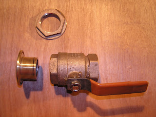
The assembly we used consists of a thru-hull, adapter flange, ball valve, and hose adapter (not shown) as shown in photo one below. Various thru-hulls and strainers are available that have the flange built into them (such as the sea cock in photo two). I opted to use a Groco adapter flange as we often sail to remote locations and it is far easier to procure a bronze ball valve from a local hardware store then it is to order one with the flange built into it and wait several days or weeks for one to arrive and have to deal with getting it through customs in foreign ports, a task that often requires hiring a customs agent at considerable expense. The adapter flange has straight thread for the thru-hull and tapered thread for the ball valve.
As a marine surveyor I often see ball valves installed directly onto thru-hulls, as shown in photo three. This is an incorrect and potentially dangerous installation and should NEVER be done. Thru-hulls are straight thread, ball valves are tapered pipe thread. When you assemble the two the threads bind almost immediately and you have two or at best three threads holding as indicated by the black line on the thru-hull in photo three. I marked this with a felt pen after tightening with tools to demonstrate how little thread is engaged. With constant vibration or a mis-step onto the fitting the joint is compromised and the vessel can be flooded very quickly.

PHOTO ONE


PHOTO TWO

PHOTO THREE