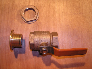
The time has come to dry fit the cockpit drain thru-hulls in order to ensure proper clearance of the ball valve handles etc. The holes in the hull were enlarged from 1-1/4" to 1-1/2" to allow for faster drainage of water when the cockpit is pooped. The hull thickness was measured, the thru-hull cut to length, and the complete assembly was dry fit into the hull.
The assembly we used consists of a thru-hull, adapter flange, ball valve, and hose adapter (not shown) as shown in photo one below. Various thru-hulls and strainers are available that have the flange built into them (such as the sea cock in photo two). I opted to use a Groco adapter flange as we often sail to remote locations and it is far easier to procure a bronze ball valve from a local hardware store then it is to order one with the flange built into it and wait several days or weeks for one to arrive and have to deal with getting it through customs in foreign ports, a task that often requires hiring a customs agent at considerable expense. The adapter flange has straight thread for the thru-hull and tapered thread for the ball valve.
As a marine surveyor I often see ball valves installed directly onto thru-hulls, as shown in photo three. This is an incorrect and potentially dangerous installation and should NEVER be done. Thru-hulls are straight thread, ball valves are tapered pipe thread. When you assemble the two the threads bind almost immediately and you have two or at best three threads holding as indicated by the black line on the thru-hull in photo three. I marked this with a felt pen after tightening with tools to demonstrate how little thread is engaged. With constant vibration or a mis-step onto the fitting the joint is compromised and the vessel can be flooded very quickly.
As a marine surveyor I often see ball valves installed directly onto thru-hulls, as shown in photo three. This is an incorrect and potentially dangerous installation and should NEVER be done. Thru-hulls are straight thread, ball valves are tapered pipe thread. When you assemble the two the threads bind almost immediately and you have two or at best three threads holding as indicated by the black line on the thru-hull in photo three. I marked this with a felt pen after tightening with tools to demonstrate how little thread is engaged. With constant vibration or a mis-step onto the fitting the joint is compromised and the vessel can be flooded very quickly.


4 comments:
Good to see your back to work on her, I hadn't seen post for little while now.
Thanks again for the tour of her and the learning gained from this blog.
Thank You.
It feels good to be back on track.
I will soon be upgrading my thru hull / seacocks on my A30 #319. I like th eadapter flange approach too. Are you going to bolt your adapter flange through the hull? or screw it to a backing plate? or just rely on the NPS thread on the adapter and thruhull to hold the adapter in place? What kind of backing plate if any are you considering using?
The adapter flange will be through bolted with silicone bronze, flat head machine screws (sometimes referred to as stove bolts).
The backing plate is integral and was made by laminating six layers of heavy biaxial cloth to the hull with West Systems epoxy. The first layer being approximately 12"x12" with each subsequent layer being smaller and the last layer being approximately 4"x4" for the 3/4" thru-hull. A layer of West System Epoxy thickened with high density filler is then applied and used to fair and level the area under the flange. This makes a very strong integral backing plate that requires no maintenance.
The laminate schedule (number of layers and type of cloth used) varies with the hull thickness and shape.
Cheers, Don
Post a Comment